
So I’ve been a proud owner of an HTC Vive for about two months now, and I’ve had my share of demos to friends and family alike. While there’s quite a few impressive SteamVR environment setups, I’m inspired this paragraph on an article about The Void:
First, the wall in front of me — a blocky, pixelated surface that was as unremarkable as a sheet of sound-dampening foam — looked the exact same as it had before I lowered the visor. The Void was accurately projecting into my visor an image of that wall that looked just like the wall I had seen in real life.
Of course, this idea is nothing new and several people had shown videos and/or uploaded their environment publicly to the SteamVR workshop. Sadly, there’s very little sharing going on about the process required to get your own virtual room up and running. This two part video series helped a lot, but it’s missing a bunch of unwritten problems that I end up having to Google out of. So as a resource for those who want to dabble in building their own virtual room, here’s the complete, zero expectation, (almost) all common glitch and hitch solved guide to building your own SteamVR Environment from the ground up:
Step 1: Map out your room
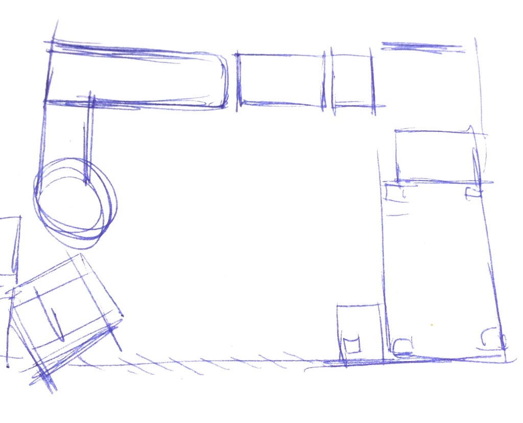
You’ll probably want one of these:

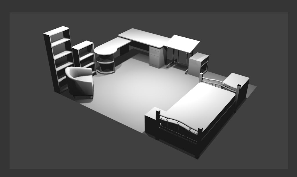
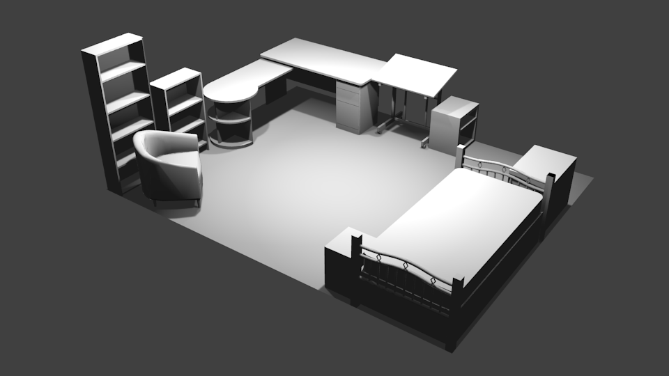
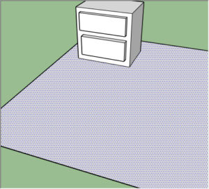
Well, not exactly this one, but you know what I mean. Now look at your own room, and roughly map out all the furniture that’d form your chaperone boundary:
 |
| (Taken using Cardboard Camera. You can download and see it in VR via this link https://goo.gl/photos/ieUiZZg67gMbaEtZ9) |
Step 2: Grab Some Software
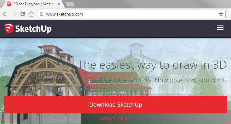

Step 3: Learn SketchUp
- First, you’ll need to select a template to get started. Use Simple Template – Meters since both Blender and SteamVR seem to favor metric measurements:

- One of the first things you need to learn in every 3D program is to move the camera around:
- To rotate, hold down the middle mouse button and drag
- To move forward or backward, scroll the mouse wheel
- To side step or go straight up or down, hold down the middle mouse and the shift key, then drag
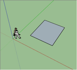
- Now, let’s practice making some stuff! The principle behind SketchUp is really simple: imagine drawing a shape on the ground, and then pulling it up to give it volume. So to make a box, you do the following:
- Select the Rectangle Shapes Tool (or press R)

- Click at one corner, move, then click at the opposite diagonal corner.
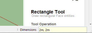
- Between the first and second click and until you start drawing or selecting another shape, you can type in the measurement numbers (the number updates at the lower right corner) of the rectangle to change its dimension. Don’t forget to press Enter to confirm the change.
- Select the Push/Pull Tool (or press P)

- Mouse over the rectangle so you see the polka dot highlight, click to start, move, then click when the height of the box looks correct. Just like drawing the rectangle, you can type in the height number directly to make precise measurements.

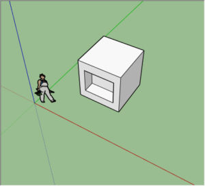
- Now that you have a volume, you can use the Push/Pull Tool to move any of the face of the box around. You can also draw more shapes on one of the box faces and push/pull again to get more complicated geometry:
- For example, after drawing another rectangle on the side and pushing it inward I’ve made myself an open box:
- To cut a hole in an object, you can either draw the hole before pulling the volume out or, if the object already exists, draw the hole and push it all the way to the face of the opposite edge. You’ll find that SketchUp really likes snapping to stuff so position your cursor over the opposite edge to snap the push distance. Instead of having a paper thin face on the far end it’d simply disappear and make a hole.

- To select and/or delete stuff, change to the Select Tool (or press Spacebar), then draw a box around the entire object to select it. Press Delete key to delete the selected stuff.


Step 4: Build Room in SketchUp
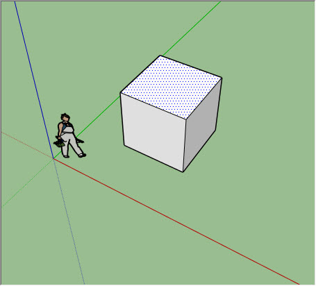
- Clean up the scene you have from all the practice shapes you’ve made. Might as well delete that lady used for scale comparison – we’re using real measurements so we don’t need her.
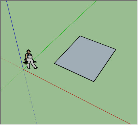
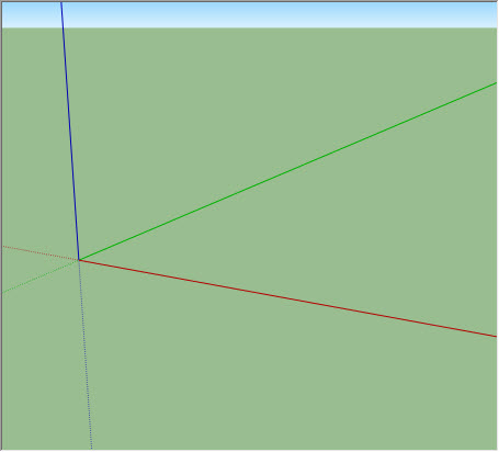
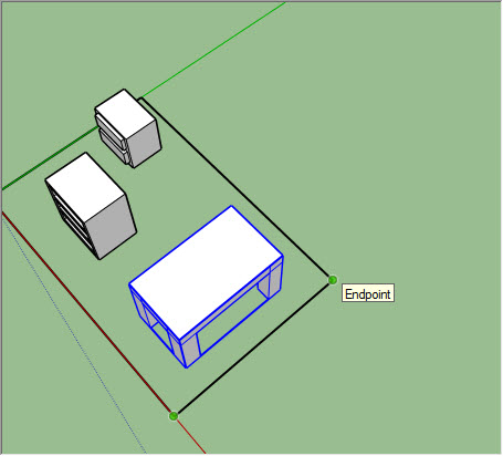
- Starting from the origin, the point where the three lines meet, draw a rectangle off the solid green and solid red line that matches the dimension of the room you want to map out.
- By the way, the three lines are your X, Y, and Z axis. An easy way to remember which line is for what axis is to remember the RGB color model – Red is X, Green is Y, and Blue is Z.
- The positive side of each axis is solid in SketchUp, whereas the negative axis is dotted.
- The positive Y axis will line up with your room scale environment’s forward direction.
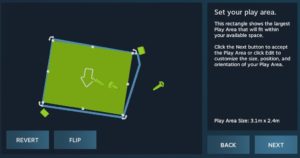
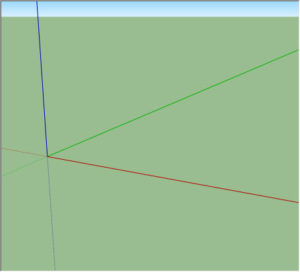
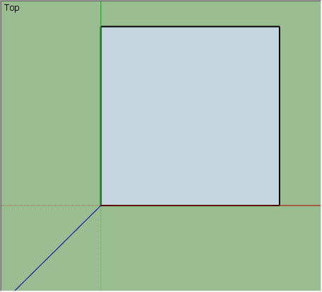
(If you don’t remember what that is, configure your SteamVR to show your play area – there’s an arrow outside of the box pointing toward the environment’s forward direction) - Point your camera down from the top, or go to the Camera menu and choose Standard Views: Top. You should notice that the color of the rectangle is a dull blue-grey right now.

-
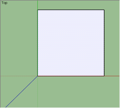
Right click on this surface, and choose Reverse Faces. The surface color should now be white. In theory, everything that you draw and pull up from this white side should be white, as well.

- This is important because of something called surface normals (you can read up on it if you care). The TLDR version of surface normals is that each surface in 3D, like a piece of paper, has a front and a back side. Putting the back side (grey side in SketchUp) on top is bad, like wearing your underwear inside out bad. Unfortunately SketchUp has a tendency to flip flop back and forth between front and back faces anyway, and you’ll have to be especially vigilant to make sure the front side of everything is facing outward at all times.
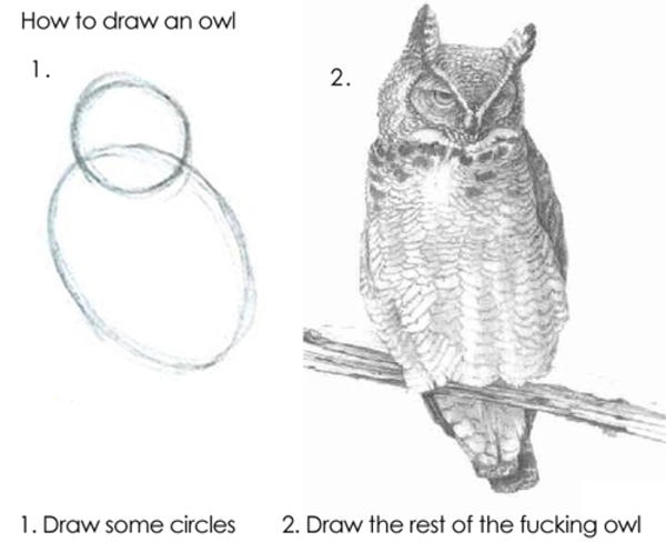
- Draw the rest of the fucking owl.
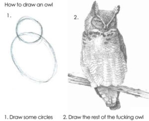
- Okay, not really, but unfortunately my room is not your room so unless everyone sends me a copy of their floor plans (please don’t) I can’t really help you model your room. Here’s some tips though:
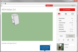
- If you’re a lover of Ikea furniture as much as I am, you’re in luck – there’s a metric ton of people who had already done the work for you. Just go to the Window menu, open the 3D Warehouse, type in the name of your furniture, and 9 times out of 10 there’s something for you to download. The key word to watch out for, though, is to-scale. You can fudge an off scale furniture by using the Scale Tool (Press S) and changing the dimensions (remember you can type in exact numbers), but it’ll never look as accurate as a to-scale model.
- If you’re really more in it to practice modeling 3D stuff for fun (like me), then focus on simple shapes, especially rectangular ones:
- Bookshelves – pull up the entire volume, then push in to hollow up space for the shelves

- Drawers and closets are similar – pull up the volume, then carve additional rectangles to push and pull to define details. A simple line won’t do – with the way we’re doing it, none of the lines would be visible at the end of the process.
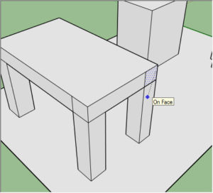
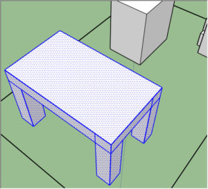
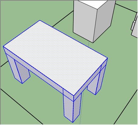
- Tables are slightly tricky – pull up the legs, then draw a rectangle in mid-air using the table corners as snap points.
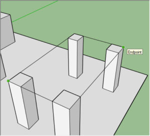
- While making sure that the same rectangle wasn’t drawn on the floor level, pull up the table surface, then pull up the legs or pull out the table corners to fill in the missing space.
- Use The Tape Measure Tool (Press T) to help you measure out spaces with lines that can be easily erased later. When you’re done, select everything, go to the Edit menu, and use Delete Guides to delete all the guides.

- It might be helpful to group up your objects so they can be moved around easily and without destroying the floor geometry underneath.
- Delete the floor surface since it’d connect your current object to everything else otherwise.
- Select one of the faces of the object you want to group, then right click, go to the Select submenu, and choose All Connected.
- Open the Edit menu and choose Make Group.
- Restore the floor by selecting the Lines Tool (Press L), then draw a line over one of the existing lines of the floor. This will redraw the floor surface.

- Once you are done (or have something you’d like to test out), Open up the File menu and select Export: 3D Model, then change the Save as type to OBJ file. Find an appropriate place to save out the model and we’d be ready to move to the next step!


Step 5: Learn Blender
 |
| Blender’s default Screen Layout with five Editors: Info (1), 3D View (2), Outliner (3), Properties (4) and Timeline (5) |
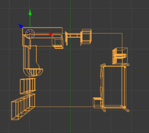
- Whenever an object is selected, there’s three axis arrows that forms around its origin point. To move the object along one of the axis, simply click and drag on one of the arrowheads. Remember, the axis order are RGB (Red = X, Green = Y, Z = Blue).
- In the Tools tab to the left edge of the 3D View, there’s a button to Translate (move) the object. Normally, it’ll move parallel to the plane that’s formed by your 3D View, but you can press X, Y, or Z to constrain your movement to one of the axis. Whenever you use one of the tools, a window would show up at the bottom left that should show the name of the command and the values applied to it. You can change the values here to modify the command much like how typing in numbers in SketchUp work.
- If you press N, a new panel should toggle on (or off) at the right edge of the 3D View. At the very top of this panel are the absolute values of the object’s position and rotation, relative to the object’s 3D origin.
Step 6: Bake Lighting into Room Model
- Fire up Blender now and load up the default startup file (if you’re already in Blender, press Ctrl+N, then Enter to confirm).
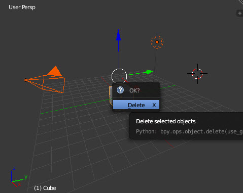
- Select everything from the default scene by pressing A until everything in the 3D view are highlighted orange, and delete them by pressing Delete, then Enter to confirm.

- Open up the File menu, go to Import: Wavefont (.obj), find the OBJ file you’ve exported form SketchUp and import it here.
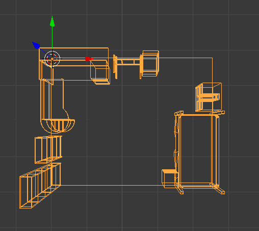
- Switch to Object Mode (it should be in Object Mode at this point), and press A until everything are highlighted orange again. This time, we’re grouping all the geometry together – press Ctrl+J. If you look through the Outliner to the top right of the Blender window, there should only be one Mesh object left in the scene; also, instead of having highlighted orange outlining individual objects and some in red while other in orange, you should get a uniform orange outline around everything.

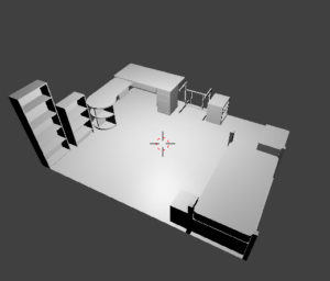
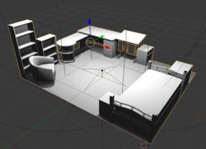
- You should now move the entire object so that the axis origin is the center of the SteamVR Play Area. The easiest way to do this is to switch directly to the Top 3D View (press 7 on the keypad) and use any one of the movement methods I’ve introduced above. Furthermore, it might be helpful to press Z to toggle between Solid and Wireframe shading. You should also know that Blender units correspond one to one to meters, so if the Room Model is 5m wide, in Blender it’d be 5.0 units wide. This scale carries all the way to the environment in SteamVR as well.
- Now, you need to align the positive Y axis to the Play Area’s forward direction. To make rotation alignment easier, we’ll now recenter the origin. Make sure the room model is selected, then Press Shift+S, then Cursor to Center. The red and white circle that is the 3D cursor should now return to the origin of the axis lines. Now, while avoiding left clicking to change the 3D cursor position, look to the left and go into the Tools tab. Under the Edit section, a new command named Set Origin should be available in black. Press the button, then choose Origin to 3D Cursor. If you check the N-panel now (toggle by pressing N), the Location of the object should be set to 0 on all 3 axis. You can now adjust the Z Rotation in the same panel to rotate the entire room around the center clockwise or counter-clockwise, in degrees.


- Time to setup some lights. Feel free to rotate the view back to a more comfortable angle, then go to the left side of the 3D View, switch to the Create tab, and scroll to the bottom to find the list of Lamps you can create. Point lights are probably the most helpful to you. Create one, move it above your Room Model, and press Shift+Z to toggle a preview of how the lights would change the model’s appearance.
-
Tweak the light’s property at the Properties panel to the right. With the light selected, you should see a lights option tab that may or may not be automatically selected. Tweak all the properties, change shadows, and maybe add more lights if one isn’t enough to light the scene the way you want it to.

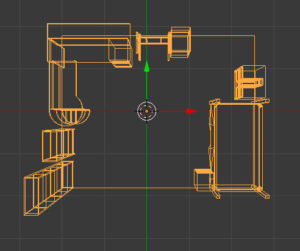
- If you’re still previewing the rendered image with lighting, switch back now by pressing Shift+Z. Select the room model and switch to Edit Mode either with the drop down or by pressing Tab:
- Press A to toggle the selection of surface geometry until everything is highlighted orange. I’m not sure why, but sometimes an object can be selected without all the faces selected as well, so this step is necessary.

-
Pull out a new view window by dragging the upper right corner of the 3D View left. Note that the windows can be split down or left, or rejoin a split window up or to the right.

-
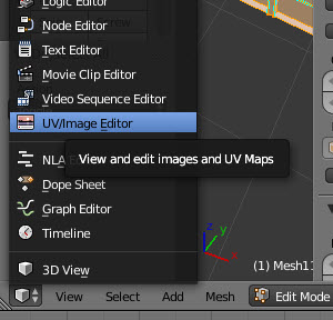
At the bottom left corner of one of the views, switch the view type from 3D View to UV/Image Editor.
-
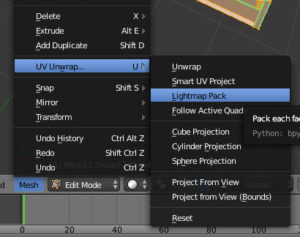
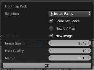
Move back to the 3D View and find the Mesh menu at the bottom. Select UV Unwrap: Lightmap Pack:
-
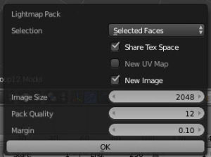
Change some options. Share Tex Space must be checked, and so is New Image. Powers of 2 numbers are usually best for anything computer related and in this case might be required – in any case, an image size of 512 is probably too small, so go with 2048 or higher power:
-
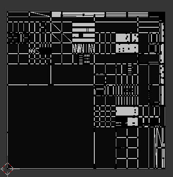
Press the OK button, and the UV map side should have a black image lined with strange shape. This is how all the shapes in the room model had unwrapped like a skin onto the 2D surface:

-
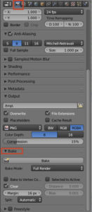
Go back to the 3D View and go to Object Mode. Go to the properties panel and find the Render tab (to the very left of the list of tabs, with a camera icon). At the bottom of this tab is a subsection titled Bake. Open it up and press the Bake button:
-
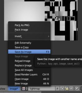
The UV map should light up like a Christmas Tree. Go to the UV map window and find the Image menu at the bottom. Select Save As Image and save the image in the same folder as the rest of your work in progress files:
-
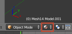
Now that the lights are baked, let’s check to make sure that it looks correct. Click the smaller icon to the right of the interaction mode drop down (You should currently be in Object Mode) and select Material.
Turn off all the lights by going to the Outliner (list of objects on the scene at the upper right corner of the Blender window) and toggling the camera icon off to the right of all the light objects.

-
Go back to the Properties panel and look for the Material tab (it uses the same orange ball icon). Look for the default material you’ve created in a previous step, and under the Shading options make sure Shaderless is checked.

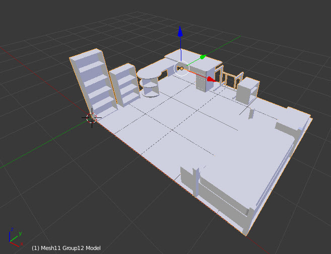
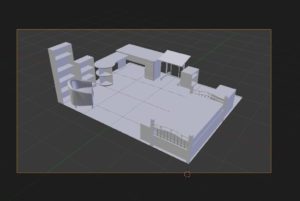
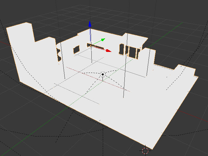
Once it goes shaderless, look back at the 3D View – your room model should now become a flat white siloette, like a paper cutout:

-
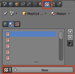
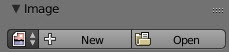
Go to the Texture tab in the Properties panel. The icon for the tab, a checkerboard square, is to the right of the Material tab icon. Press the plus button to create a new texture.
Make sure the type is Image or Movie (it should be the default), then go under the Image section and use the Open button to load the UV map you just saved a few steps ago.
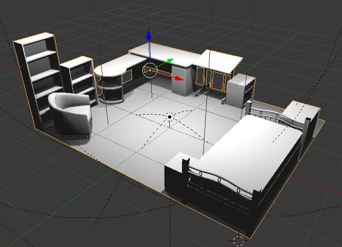
Your 3D View should look “normal” again, even though now there’s no real light in the room and the shading is applied by directly with flat colors onto the model’s surface. You can see the effect when you try to turn on the lights again but still see no change to the shading:
-
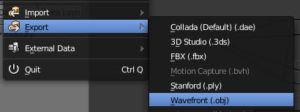
Once you see this, the model is now ready for export. Go to the File menu and choose Export: Wavefont (.obj). You should save this file to a more finalized location where you’d be importing the file from SteamVR.
-
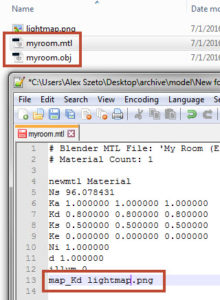
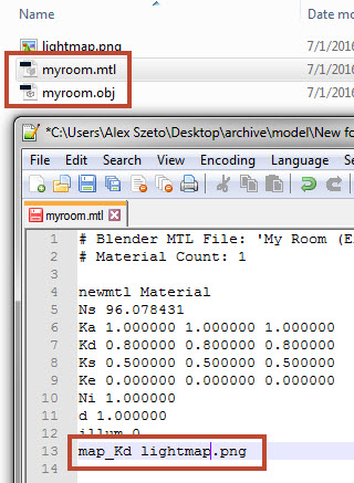
The export action should generate two files in the target folder: the object (OBJ) file and the material (MTL) file. Open the material file with a text editor (Notepad works, although it would scrunch all the text into a single line) and at the very end of the file look for the words map_Kd and make sure that if there’s an absolute path to the file (C:Some Folderlightmap.png), change it to just the name of the file (lightmap.png).
-
If the UV map file (lightmap.png) isn’t already placed in the same folder as the OBJ and MTL files, do so now.
-
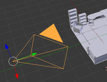
Finally, we’ll need a screenshot of the scene to upload to SteamVR. While pressing Print Screen and cropping the 3D View in Paint does the job, let’s learn one more thing about Blender and set up a real camera for rendering. Collapse the panels by dragging the upper right corner of the left window toward the right, then select the Create tab from the left side of the 3D View, scroll to the bottom of the list, and click Camera to create a new camera.

-
Make sure that you’re in Object View, and either left click on the camera in the Outliner or right click the camera object in the 3D view to select it.

-
Ignoring where the camera is sitting now, change your 3D View to show where you’d roughly want to make a render of the room model, and press Ctrl+Alt+Nuimpad 0. This should move the camera object right on top of your current 3D View camera. You should see a rectangle highlight and the rest of the scene darkened. The rectangle is the image that would be rendered by the camera.
-
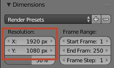
To adjust the camera, first let’s adjust the image size that’s exported by the camera. Go to the properties panel and select the Render tab (again, camera icon) all the way to the left of the tab list. You’ll find the image resolution under the Dimensions section. I actually have not figured out how to fill the workshop image display area, but in any case a 1080p screenshot seems like a good idea, so let’s go with an X resolution of 1920 and a Y resolution of 1080.
-
Now, go back to the 3D View. There’s two useful method for adjusting the currently selected camera in this preview mode. To zoom in and out, press G, and then click the middle mouse button. Moving the mouse now would pan the camera in and out. Once you’re satisfied with the size of the region being captured, left click to confirm. If you press G only, you can move the camera sideways to adjust the content that’s being captured. You’ll need to left click again to confirm.
-
Once you are happy with the view that’s inside the rectangle, press F12. Wait a bit and it should go into a different view that shows the result of the final render.
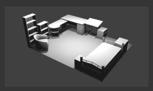
Similar to the UV image view, you can find an Image menu at the bottom of the view – open it and choose save as image.

File format shouldn’t matter, but I used PNG and JPG is probably fine as well. Name it something new and save it along with your room model’s OBJ, MTL, and PNG files – it’s easier to locate them all this way.
-
To return from the final render view back to the normal 3D View, press Escape.
-
Time to upload! Start SteamVR, open the menu, and choose Workshop: Upload New.
-
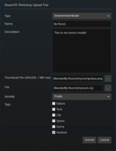
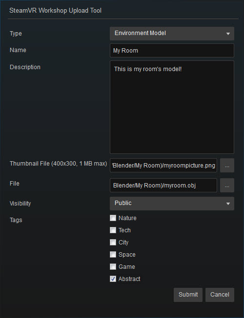
The upload tool would pop up. Most of the fields should be self explanatory so fill them out as you see fit. For Thumbnail File, open the image you’ve saved for the final render; for File, open the OBJ file.
-
Once you hit submit, you’ll be sent directly to your new SteamVR environment’s Workshop page inside Steam. You can now subscribe to it, and change your environment to your new room model using the Customize options within SteamVR
-
Walk toward your chaperone boundaries to trigger it. The actual location of your room model objects are probably going to be off by a dozen or more centimeters, and if you’re careless, the virtual objects may be rotated to a different section of the physical room. Since your Vive controllers are visible in both virtual and real world, they can be handy units of measurements to calculate the offset of your virtual room compared to the real one.
-
Now that the lights are already baked, adjust the room model relative to the origin of the scene by the offset you’ve measured earlier inside SteamVR. You’d find that moving just the room model in Blender no longer changes the lighting, because it’s still showing the baked lighting from earlier. Reset the origin (Shift+S Cursor to Center, left Tools tab Set Origin: Origin to 3D Cursor) before rotating if you need to rotate the room after shifting the origin as well. To re-rotate a room that’s been rotated in the past, reset the rotation in the N panel (the one you open by pressing N) to 0 before shifting Origins so you don’t lose track of your room’s rotation.
-
After exporting the OBJ file, don’t forget to reset the image referenced by the MTL file – it might be easier to export the OBJ file elsewhere and only copy the OBJ file over to where you’d load it in SteamVR, to keep the MTL from updating on every export. The rest of the files can be left alone.
-
If there are changes, once the changes are exported with the OBJ model go back to SteamVR menu and choose Workshop: Modify Existing instead. Some of the fields should be filled out with old data, but the Thumbnail file and the File are always required. When you return to the Workshop page, the fastest way to see the changes in SteamVR is to unsubscribe then resubscribe to the same environment. If that still doesn’t work, closing and then restarting SteamVR should do the trick.
-
You are now the proud owner of a fully personalized SteamVR environment. Congratulations!


Thanks heaps. Just what I have been looking for.
Very cool! I'm going to give this a try!
Best I've seen so far – Thanks!
I have express a few of the articles on your website now, and I really like your style of blogging. I added it to my favorite’s blog site list and will be checking back soon… עלות בניית שלד
This comment has been removed by a blog administrator.
One of the very first judgements we make as internet marketers involves the critical choices in designing websites. Elyn Jordan Jessa